Anybody who has ever saved an image has seen the file format JPEG before. It’s one of the most common file format for images along with .PNG. In this post, I’d like to delve a little deeper into its history, why it’s used, and how it works.
A little history
JPEG stands for Joint Photographic Experts Group and was created in the 1992 because there was a need for a standardized image format that could reduce the file size of digital images and still retaining image quality. Prior to JPEG, there was .BMP which worked and was high quality, but the issue was they were large in size as .BMP are rasterized, uncompressed and therefore lossless.
Although digital photograph predated JPEG by ~20 years, JPEG sought to solve the following issues:
- File Size Reduction: Compress images so they are easier to store, load and transfer in the digital world
- Standardization: A single, reliable and universal format that could be used across different devices, such as computers, cameras and phones
- Web Friendly: Practical to use on the internet and through digital communication
- Lossy Compression: It’s able to preserve visual quality despite discarding less perceptible visual data.
- Metadata: Allow embedding of important information such as date, name, etc.
Ok, but how does it work?
JPEG in a lot of ways seems to be a black box when it comes to encoding and decoding, and to be honest, the mathematics behind the signal processing in JPEG is really quite complex and extends far beyond what I hope to cover in this blog.
I will try to cover this in two manners: First in layman’s terms, and second in scratching the technical surface.
JPEG takes advantage of the fact that human eyes are not perfect, and exploits this fact by removing information that our eyes are not great at perceiving. This information is twofold, human eyes are:
- Less sensitive to color than brightness, and,
- Not good at perceiving high frequency data in images
Eyes have two different light detecting cells called photoreceptors, specialized for different vision tasks: Rods are brightness sensitive, handle low light, night vision and cones handle bright light, color vision and sharp detail.

In each eye, there are 100M rod cells vs only 6M cone cells which means there’s ~16.7x more rod cells to cone cells making the human eye much more sensitive to brightness of an image than color.
In the world of photography, brightness and darkness is called luminance, whereas the color can be called chrominance. In the image below, there are 4 images: (1) Original, (2) Luminance, (3) Cb-Chroma Blue, (4) Cr-Chroma Red. What you’ll notice is (2) Luma shows a greyscale image that has sharp detail despite the lack of color, wheras the latter two, do not.

We can take this concept above and take a more detailed look into the 5 key steps of the JPEG compression algorithm:
- Color Space Conversion (RGB to YCbCr)
- Chrominance Downsampling (Reducing Color Data)
- Discrete Cosine Transform (DCT) Converting to Frequency
- Quantization (Discard Less Important Data)
- Entropy Encoding (Lossless Compression)
Admittedly, steps 3 through 5 can get a little complex, so I’ll do my best to simplify things.
1. Color Space Conversion
Simplified: Humans are much better at distinguishing brightness than they are colors. In monitors, the RGB color space is used, but this color space is not the most efficient for human eyes as it has more color than the human eye can see, thus there is potential to discard unnecessary information by converting the RGB color space to the YCbCr color space. The reason for this is YCbC separates luminance components from color components and thus allows color to be altered independently of brightness. In separating the two components, color detail can be discarded independent of brightness.
Technical: Images typically are viewed in a 24 bit RGB color space, that is: 8-bit Red, 8-bit Green, 8-bit Blue giving a maximum of 2^8^3 = 2^24 = 16.7M colors. The image below shows the gamut of colors in a 24 bit RGB color space where you can see the diagonal from (0,0,0) to (255,255,255) represent the greyscale luminance from darkest to brightest
![(a) RGB Color Space [7]; (b) YCbCr Color Space [8]](https://www.researchgate.net/profile/Deise-Maia/publication/298734907/figure/fig1/AS:341749898727436@1458490933430/a-RGB-Color-Space-7-b-YCbCr-Color-Space-8.png)
Unfortunately, the human eye can only distinguish about 10M colors which doesn’t make the RGB color space the most efficient way to save or transmit images as RGB can display 6.7M more images than the human eye can even see!
Enter YCbCr
Evolved from a system called YUV. YCbCr uses 3 separates pieces of information for each pixel similar to RGB:
- Y: Luminance – contains value for brightness of the pixel such as the greyscale image
- Cb: Chrominance blue component
- Cr: Chrominance red component
This color space is a bit more abstract as you can’t simply mix the components together to get the final color. In order to transform RGB to YCbCr, you need special formulas:


The beautiful thing about YCbCr, is the luma component of each pixel is encoded separate from the color component. Brightness information and color information can be changed independently as you can recall, our eyes are much more sensitive to brightness than color.
Since you can now alter the color detail independent of brightness, you can generate an image still looks good to humans, but with less data.
2. Chrominance Downsampling (Chroma Subsample)
Simplified: Chroma subsampling exploits the fact that humans do not see color well, and thus removes color detail and resolution to save data.
Technical:
In the image below, you can see a grid represented by a 4 x 2 grid where the 4:X:X dimension can be represented as a:b:c where:

a. The number of pixels across that are being sampled
b. How many pixels have their own chroma sample, and,
c. How many pixels in the second row have their own chroma sample
So,
4:4:4 – Best pixel information but high data rates
4:2:2 – High quality, and lower file sizes. This is broadcast quality
4:2:0 – Low pixel, small file sizes – wouldn’t notice on smaller images
You can take this idea of chroma sub sampling and apply a compression from 4:4:4 to say, for example, 4:2:0 which would effectively take pixel blocks of 2×2 dimension in a 4:2:0 state such as in the image above showing chroma where a block of 2×2 pixels containing 4 different colors is converted to a single color. In chroma downsampling, the single color can be generated by taking the average of the color. In chroma subsampling, the single color is typically generated by using the color of the top left pixel to be the color of the entire 2×2 block.
This is a lossy compression technique which means you will lose data from the original image.
Compression Rate From Chroma Subsampling
If you take Y, Cb, and Cr components and split them each into its own 8×8 pixel grid, I screenshot this image from Reducible’s video on JPEG compression showing how chroma sub sampling alone will get you a 50% reduction in image size.
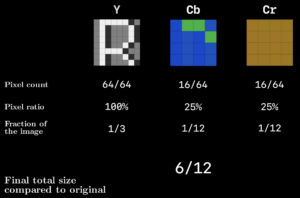
A 50% reduction size, but it still leaves a 48MP image at 24MP, which is still a large file size.
3. Discrete Cosine Transform
Simplified: The Discrete Cosine Transform is rather complex and abstract, but what it does is exploits the fact that (a) Low frequency is more common in real world images, and (b) humans are less sensitive to high frequency detail. High frequency would be in reference to the rate of change between pixel values with respect to spatial position.
Take the following collage as an example, humans have a hard time picking up fine detail with sharp changes in pixel value relative to the overall image.
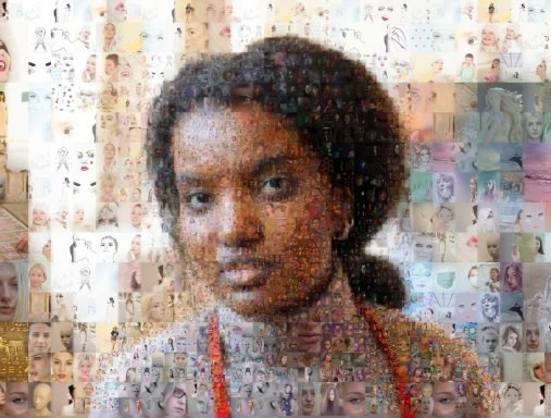
This is an image that contains many smaller detailed images within it, but it’s quite hard to notice what the detail in the smaller images is. This is the premise of the Discrete Cosine Transform.
An image can be converted into an arbitrary wave function (or signal) based on its pixel value and the DCT is able to recreate this wave function by taking advantage of a very clever fact that all frequencies can be created by a combination of 8 standard cosine waves frequencies to generate coefficients to represent the frequency. By converting the wave to a sum of these coefficients, you’re able to quantize, or remove information in order to save data.
Technical:
Take a greyscale image where the brightness value is an 8 bit value ranging from 0 to 255. A high frequency image will show rapid changes in pixel value, whereas the lower frequency will be more linear.

A Discrete Cosine Transform is based on the same principles as the Fourier Transform where it takes a set of fundamental patterns that can make up any signal based on a weighted sum of coefficients of the fundamental signals.
The first step required for a DCT is first to generate a signal, or wave function, based on the input image. A rational way to do this is by taking a sample size of an image as an 8 x 8 pixel grid, where each row of pixels can generate some signal – this is the idea behind discretization.
As a subset of the 8×8 grid, we can start with a single row of 8 pixels in which you can generate a signal based on its pixel values, such as that shown in the image below.

The signal is discretized into 8 data points where we can approximate some signal. We can use this approximated signal to input into the DCT.
The DCT was invented by Nasir Ahmed who discovered that any cosine wave function was just a weighted sum of 8 fundamental cosine patterns. When you run a signal through a DCT, the DCT generates the values for the coefficients to represents the number of each of the 8 fundamental cosine patterns. This is the basis for a 1D DCT.
In JPEG compression, this same principle is taken for an 8×8 matrix as mentioned earlier into what’s called a 2D DCT, but there are 64 coefficients in an 8×8 grid. The DCT first runs through each row, then subsequently through each column, generating a grid of coefficient values.

The output is results in energy compaction, the premise that most of the largest values are concentrated in a few low frequency coefficients. The concept of energy compaction is extremely important in compression to retain high visual quality.
An interesting observation is that by the time a small number of coefficients are incorporated, the signal and image look pretty close to the original image, and this is the basis for compression through DCT. As shown in the image below, there is little visible variance between the compressed image and the original image at just 25% of the coefficients used.

3. Quantization
The process for removing high frequency components in jpeg is called Quantization.
Quantization accomplishes this by for example, taking an 8×8 matrix and dividing each element by a scalar value from a quantization table and round it to an integer. This results in loss of data but retains the majority of the low frequency data which shapes the image, as described by energy compaction.
Quantization table are provided by the JPEG standard from visual experiments and this is how JPEG derives the quality of JPEG. High quality compression parameters can be translated to lower quantization table values, and the output of the transformation is quantized DCT coefficients which contain mostly low frequency values which allows for further compression through redundancy.
4. Entropy Encoding (Lossless Compression)
The last step involves:
- Run length encoding, and,
- Huffman encoding

The matrix of quantized DCT coefficients works well for run length encoding as many of the high frequency elements have been zero’d and thus order the coefficients in a zig zag manner to maximize the chance of a large sequence of zeroes.
JPEG does use a specific JPEG run length encoding which compresses further.
Last, the compressed run length encoding is used as an input into a Hoffman Encoding, the specifics in which won’t be discussed in this blog as it does get quite complex.
5. Conclusion
I hope after you’ve had a quick primer into the JPEG format, you can appreciate how complex the math behind the compression really is and give you some insight as to what’s going on behind the scenes everytime you save an image as a JPEG.
References
- https://illumin.usc.edu/jpeg-the-timeless-insights-that-make-us-still-use-a-format-from-1992/
- https://www.youtube.com/watch?v=0me3guauqOU